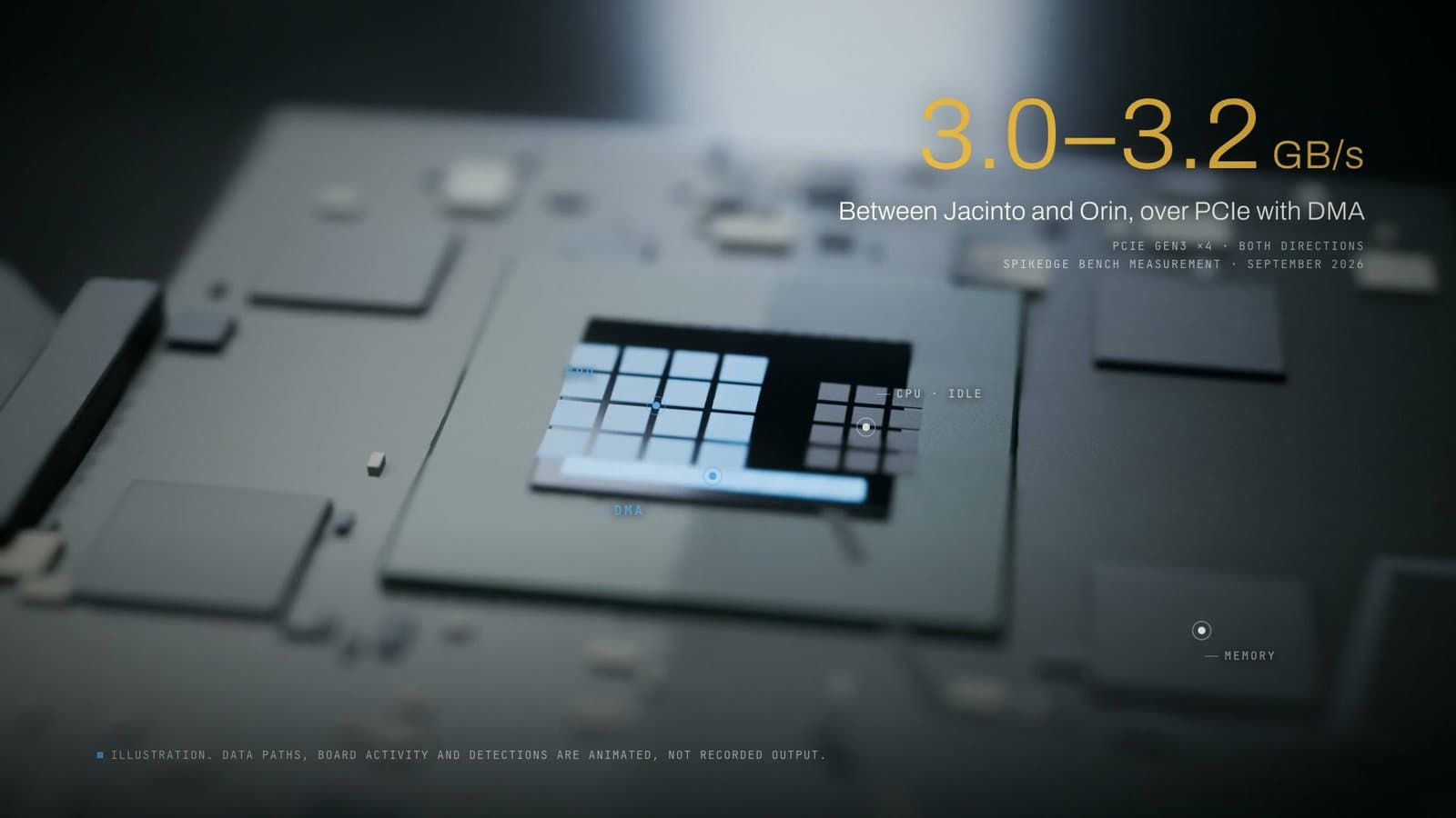
In EtherCAT, the master sends one Ethernet frame per cycle, and every device on the line shares it. As the frame passes through a device, the device's EtherCAT Slave Controller (ESC) reads its output data, writes its input data into the same frame and forwards it without stopping, all in hardware. The last device sends the frame back, and the master checks the Working Counter to see whether every device did its part. On our bench (TI AM572x master, one slave, 64 bytes of process data, 10 kHz) the frame took 19.2 µs on average and 30.9 µs at most from send to full return.
In short
- The whole line shares one frame: with the FMMU, one datagram carries every device's process data, and each device reads and writes its part in hardware as the frame passes.
- The Working Counter counts the devices that processed a datagram; if it does not match, that cycle's data is not fresh.
- Classical CAN carries at most 8 bytes per frame, CAN FD up to 64, and nodes share the bus through identifier-based arbitration. For distributed ECUs in a car it is still the right tool.
- On our bench (1 slave, 64 B, 10 kHz): 19.2 µs average, 30.9 µs maximum, 25.5 µs total with master software. Data size moved latency far more than cycle frequency.
Why does a machine need one shared "when"?
The 80-second film at the top of this page opens with one line: a machine is a set of parts that must agree on when. If the six axes of a robot arm do not move on commands from the same cycle, the tool leaves the programmed path.
In the classic Ethernet-based approach, each device gets its own packet and sends its own reply. Packets queue in a switch, so latency depends on the queue, and every Ethernet frame is at least 64 bytes even if a device needs only a few. EtherCAT's answer is one frame per cycle with a slot for every device.
Worked example (not a measurement): 30 devices, each takes a 4-byte command and returns a 4-byte status; preamble and inter-frame gap are left out. With one frame per device, 30 × 64 = 1,920 bytes leave the master. One EtherCAT frame is 14 + 2 + 10 + 240 + 2 + 4 = 272 bytes (Ethernet header, EtherCAT header, datagram header, 30 × 8 = 240 bytes of data, Working Counter, FCS) and comes back carrying the replies. The master sends a little under one seventh of the bytes. The ratio is about line efficiency, not latency.
The film follows this idea through a plant: the frame leaves the control cabinet, runs the servo drives, the six axes of the arm welding a car body and the thirty joints of a humanoid, and ends in the car the line just built. The cabinet, arm, humanoid and car are our own 3D illustrations; the thirty joints are not a product claim. The bench numbers are real and ours (film page).
What is inside the one frame?
EtherCAT puts its data in a standard Ethernet frame with EtherType 0x88A4. Per Beckhoff's ESC data sheet, the 14-byte Ethernet header is followed by a 2-byte EtherCAT header (length and type), a datagram area of 14–1,498 bytes and a 4-byte FCS. The datagram area holds one or more datagrams, each with a 10-byte header (command, address, length), 0–1,486 bytes of data and a 2-byte Working Counter.
Device addressing handles configuration and status. Process data uses logical addressing: all devices share one 4 GB logical address space, and the FMMU (Fieldbus Memory Management Unit) in each slave maps a slice of this process image into local memory, down to single bits. The master sets up the mappings at start-up. One LRW (logical read-write) datagram then reaches ESCs anywhere on the line in a single pass, and the master never collects data device by device.
Processing on the fly: the frame never waits
ETG describes it this way: each slave reads the data addressed to it "on the fly" and inserts its own data as the frame moves on; the frame is delayed only by hardware propagation time. Beckhoff's data sheet gives the hardware side: the ESC does not store the frame, data is read and written as the bits pass, and there is not even a transmit FIFO. So every slave needs an ESC: an ASIC, an FPGA or a block inside a microcontroller. In the TMS320F28388D on our bench, the ESC sits inside the C2000 microcontroller.
The SyncManager controls traffic between ESC memory and the slave's processor. Cyclic process data (PDO) uses buffered mode (three buffers), so the reader always gets the latest consistent data. Configuration and diagnostics run outside the cycle in handshaked mailbox mode; CoE uses it to carry CANopen's object dictionary, PDO mapping and SDOs. A buffer change is accepted only if the frame's FCS is correct, so a corrupted frame never leaves a half-written buffer.
The return trip is hardware too. The line is full duplex. A closed port sends nothing out and passes the frame internally to the next port; in automatic mode, a port without a link counts as closed. At the last device the free port is closed, so the frame turns back by itself. A two-port ESC processes the frame on the way out and only forwards it on the way back.
Working Counter: how does the master know the work was done?
Every datagram ends with a 16-bit Working Counter (WKC). The ESC increments it in hardware on success: 1 for a read, 1 for a write, up to 3 for a read-write (1 for the read, 2 for the write). The master computes the expected value in advance. If two slaves are both read and written in one LRW datagram, it expects 3 + 3 = 6; if one fails to process its part, 3 comes back. The counter counts devices, not bytes.
/* Skeleton of a master cycle (pseudo code) */
for (;;) {
    wait_cycle_tick();                      /* e.g. 10 kHz: every 100 µs */
    put_outputs(&frame, app_outputs);       /* one LRW datagram */
    send(&frame);
    if (!wait_return(&frame, deadline)) {   /* frame did not return */
        lost_frames++;
        keep_last_valid_inputs();
        continue;
    }
    if (frame.wkc != expected_wkc) {        /* a device skipped its part */
        mark_inputs_stale();                /* never pass old data as fresh */
        if (++wkc_errors >= WKC_LIMIT)      /* the machine sets the limit */
            enter_safe_state_and_diagnose();
        continue;
    }
    wkc_errors = 0;
    app_update(get_inputs(&frame));         /* consistent cycles only */
}
Why does the car use a different bus?
In the film the frame's journey ends in the car, where a different bus takes over: CAN sends eight bytes per message, one message at a time, and everything else waits its turn. The comparison is structural, not a measurement.
In Classical CAN (CAN CC) a frame carries 0 to 8 bytes of data. The 11-bit or 29-bit identifier (ID) describes the content and sets the priority: the lowest value wins. When nodes start at the same time, their identifiers are compared bit by bit; the losers become receivers of the current frame, and the winning frame continues undamaged. Receivers confirm correct reception with a dominant bit in the ACK slot. CAN FD raises the data field to 64 bytes and can switch to a higher bit rate in the data phase, while arbitration stays limited to 1 Mbit/s. According to CiA, both are standardised together in ISO 11898-1:2024; CAN XL extends the data field to 2,048 bytes.
This fits a car: ECUs send messages at independent moments, an urgent message wins by its identifier, and every message reaches all nodes. CiA calls CAN the dominant serial network for embedded control in passenger cars. The two buses can even share a chip: the TMS320F28388D on our bench has two CAN modules and one CAN FD (MCAN) module next to its ESC.
| EtherCAT | Classical CAN / CAN FD | |
|---|---|---|
| Who sends | Only the master | Any node; simultaneous starts go to arbitration |
| Data per frame | Up to 1,486 bytes per datagram | 0–8 bytes; up to 64 with CAN FD |
| Confirmation | WKC: devices that processed it | ACK: at least one receiver got it right |
| Design goal | One controller driving a machine cycle by cycle | Distributed ECUs sending independent messages |
We discuss which bus fits where in our industrial protocol selection framework (in Turkish).
What did we measure on the bench?
We do not sell an EtherCAT master. We bring lines up on TI silicon and characterise their timing; that is our industrial protocols work, and the film's numbers are a bench record of it.
- Master: TI Sitara AM572x IDK (PRU-ICSS), TI-RTOS; a commercial Class B EtherCAT master stack. Under ETG.1500, Class B is the "minimum" master class, where distributed clocks (DC) support is conditional; our setup does not use DC.
- Slave: TI Delfino TMS320F28388D (integrated ESC), Beckhoff SSC v5.13.
- Link and tools: 100 Mb/s full duplex; Code Composer Studio 12.8.1, Blackhawk XDS560v2.
| 1 slave, 64 B process data, 10 kHz | Value |
|---|---|
| Frame, send to full return (min / avg / max) | 18.5 / 19.2 / 30.9 µs |
| Total including master software | 25.5 µs |
| Slave synchronisation error | 1 µs maximum |
| Packet loss | 0% across our measurements |
We publish the maximum, not only the average. On a control loop the average is the number that makes you comfortable; the maximum is the number that decides whether the machine ships.
Transmission latency runs from sending the frame until all of it has returned and excludes master software. Total adds the average master software time to the average transmission latency; it is what the application sees. The difference is the software share: here 25.5 − 19.2 = 6.3 µs, and across all our tables it stays between 6.1 µs (128 B: 27.3 − 21.2 = 6.1 µs) and 6.4 µs (1 kHz: 26.1 − 19.7 = 6.4 µs). The transmission part grows as conditions change; the software share stays almost flat.
What we report as jitter is the slave synchronisation error (1 µs maximum). The min/max range is not jitter but the spread of the round-trip time, and the 1 µs is not a DC result. The method is in our measurement methodology article (in Turkish); our TI work is on the Texas Instruments platform page.
What do the numbers tell a line designer?
The rows come from our three measurement tables; the size is the bidirectional process-data label from the bench record.
| Condition | Avg (µs) | Max (µs) | Total (µs) |
|---|---|---|---|
| 1 slave, 64 B, 1 kHz | 19.7 | 28.5 | 26.1 |
| 1 slave, 64 B, 10 kHz | 19.2 | 30.9 | 25.5 |
| 1 slave, 32 B, 10 kHz | 18.0 | 27.7 | 24.3 |
| 1 slave, 128 B, 10 kHz | 21.2 | 32.1 | 27.3 |
| 1 slave, 512 B, 10 kHz | 34.1 | 43.4 | 40.3 |
| 2 slaves × 32 B, 10 kHz | 19.3 | 33.3 | 25.5 |
| 2 slaves × 64 B, 10 kHz | 21.2 | 35.1 | 27.4 |
Frequency does not add latency. From 1 kHz to 10 kHz the average goes from 19.7 µs to 19.2 µs; the maximum moves between 28.5 and 30.9 µs, and we read no trend into that. What shrinks is the cycle: the period drops from 1,000 µs to 100 µs, and so does the time left for the application. You pay for speed in the cycle budget.
Data size drives latency. From 32 to 512 bytes, the average rises from 18.0 µs to 34.1 µs and the maximum from 27.7 µs to 43.4 µs. Every byte in the PDO map travels every cycle, so unused signals should leave the map.
The second device hides in the average. With equal total data, the second slave adds 19.3 − 19.2 = 0.1 µs to the average, and 2 × 64 B matches a single slave with 128 B (21.2 µs). The maximum disagrees: 33.3 µs against 30.9 µs, and 35.1 µs against 32.1 µs. This data cannot tell us why, but it shows the risk of sizing a line by the average.
The 1,498-byte limit. One frame's datagram area is at most 1,498 bytes, headers included. With 1 slave × 1024 B and with 2 × 512 B, the bidirectional data went over the limit, the transfer split into two frames, and packets were lost at 10 kHz; we had to drop to 6.6 kHz and 5 kHz respectively. Size the PDO map with both directions summed and keep a margin below the limit.
Where it goes wrong
- Reporting the average as the only number. The same condition (1 slave, 64 B, 10 kHz) appears in two of our tables: average 19.2 µs in both, maximum 30.9 µs in one and 29.1 µs in the other. A series maximum is not a worst-case bound, only the worst value that series saw.
- Asking a stack without DC for a DC number. A DC synchronisation figure from a setup without DC cannot have been measured.
- A PDO map larger than one frame. On our bench it caused packet loss at 10 kHz and forced a lower frequency.
- An application that ignores the WKC. It treats a cycle in which a device skipped its part as fresh data.
- Cabling and topology errors. Beckhoff ESCs do not evaluate MAC addresses, so no unmanaged switch may sit between the master and the first slave or between slaves, and an ESC on an office network causes a broadcast storm. For diagnostics, use station addresses, not position addresses; positions shift when loops close temporarily.
What this article cannot tell you
- We measured one and two slaves, not a line with hundreds of devices; this data does not support multiplying the 0.1 µs average cost by a hundred.
- We have no DC measurement.
- We have no comparative measurement against standard Ethernet; the Ethernet column in our EtherCAT case study is a structural description, not a measurement.
- We have no worst-case number including the software path: 25.5 µs is the sum of two averages.
- We measured nothing on the CAN side; in the film, only the bench numbers are measurements.
- A different board, stack version or PDO map gives different numbers.
Frequently asked questions
What does "processing on the fly" mean in EtherCAT?
The frame is processed without stopping at any device: each slave's ESC hardware reads its output data and writes its input data into the same frame as the bits pass, and never stores the frame.
What is the Working Counter for?
The 16-bit counter at the end of each datagram counts the devices that processed it successfully. The master compares it with the expected value; if they differ, that cycle's data is incomplete or stale and must not be used as fresh.
Why doesn't EtherCAT replace CAN?
They were built for different jobs: EtherCAT for machines where one controller reaches every device with one frame each cycle, CAN for distributed networks where any node can send its own message and the identifier sets the priority.
Do these numbers apply to my line?
Not directly. They characterise one setup (TI AM572x master, a commercial Class B stack, one or two TMS320F28388D slaves, 100 Mb/s); the answer for your line comes from measuring your SoC with your PDO map and device count.
Sources
- ETG: EtherCAT Technology: processing on the fly, frame return, logical addressing, CoE.
- Beckhoff: ESC Hardware Data Sheet Section I, v2.5: datagram layout, WKC, FMMU, SyncManager, topology warnings.
- ETG.1500: EtherCAT Master Classes: Class A/B and DC support.
- CiA: CAN CC: 8-byte data field, identifier, arbitration, ACK.
- CiA: CAN FD: 64 bytes, bit rate switch, ISO 11898-1:2024.
- CiA: CAN data link layer generations: non-destructive arbitration, CAN XL.
- TI: TMS320F28388D: integrated ESC, CAN and CAN FD modules.