Cooperative perception lets a vehicle learn about an object its own sensors cannot see, from a message sent by a node that can. For a forklift behind a blind corner the problem is geometry, not model quality: no camera, lidar or larger neural network sees through a container stack. The fix is a second point of view, a mast at the corner that sees the corridor and sends the object's state. The hard part is time and coordinates: a received track describes the past, and the receiver must move it into its own frame and forward to now. Silence does not mean the road is clear.
In short
- Occlusion is geometry; a better model cannot find an object that is not in the sensor data.
- The mast sends object state, not video: identity, class, position, velocity, heading, uncertainty, observation time, frame.
- A received track is in the past; the receiver moves it into a common frame, predicts it to now and grows its uncertainty.
- Detection is not the decision; the decision is whether two corridors want the same space at the same time.
- Silence means "unknown"; cooperative perception does not replace the safety chain.
Why can a larger model not see behind a wall?
In the film, an autonomous terminal tractor approaches a T-junction in a container terminal. A stack three containers high on its right hides a forklift coming down the corridor; there is no line of sight between them.
A camera cannot look through a container and a lidar cannot return points from behind a wall; radar reflections off metal surfaces do not place a hidden object reliably. A larger neural network cannot find an object that is not in the pixels; at best it guesses. The question changes from "how do I improve the model?" to "where can I see this corridor from?". A tall mast at the corner can see both sides of the stack.
How the film was made. We did not draw the lines of sight by hand: in Blender, ray casting at every half second of scene time tested what each sensor could actually see. As the forklift nears the junction it leaves the mast camera's field of view and the wider radar takes over the track; that handover was not in the script, it came out of the geometry. These are observations about the scene, not system measurements. ETSI TS 103 324 (clause 7.1.6) notes that shadowed regions can be computed the same way, with rays.
What does the roadside perception node do?
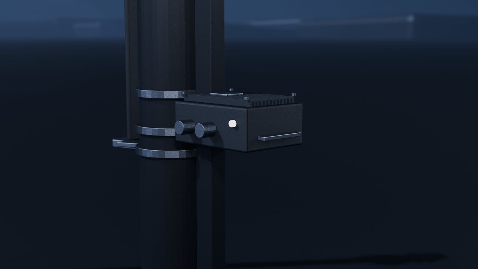
The mast carries a camera, a radar and a small computer. Different physics fails in different ways. A camera measures angle and appearance directly and infers range and speed; it struggles with darkness, glare and a dirty lens. A radar measures range and radial velocity (Doppler) directly; it is weak at classification and can produce ghost targets off metal. The node keeps what the two agree on: the camera does not confirm the radar's ghost, and the radar narrows the camera's range uncertainty.
Tracking turns detections into tracks. An object associated over time, with its state and uncertainty estimated by a filter (for example a Kalman filter) and a stable identity, is a track. When the object leaves the camera's view and stays only in the radar's, as in the film, the track must keep its ID; otherwise one forklift becomes two at the receiver. We describe this pipeline on our sensor fusion page.
What leaves the mast: video or object state?
The vehicle needs the state of the object, not pictures.
| Criterion | Video stream | Object state |
|---|---|---|
| Bandwidth | High, varies with the scene | Low; objects × message rate |
| Latency chain | Encode, network, decode, inference again | Inference at the mast, serialization, network |
| Work at the receiver | Detector, camera calibration, tracking | Frame transform, time prediction, fusion |
| Privacy | People, faces, number plates | No image; class and kinematic state |
| Time information | Frame time; event time must be derived | Observation time is a field |
| Debugging | Easy to check by eye | Needs logging and replay |
Worked example: assume 100 bytes per object, 20 objects and 10 messages per second: 100 × 20 × 10 = 20,000 bytes/s, or 160 kbit/s. Assuming 4 Mbit/s for video, the difference is about 25×. Video belongs on the human operator's screen (see our WebRTC case study).
Minimum fields (pseudocode, not the field names of any standard):
typedef struct {
    uint16_t node_id;
    uint32_t seq;             /* catches loss and reordering */
    uint32_t track_id;        /* survives the camera -> radar handover */
    uint8_t  cls, cls_conf;
    uint64_t t_obs_ns;        /* observation time: TAI, PTP-disciplined clock */
    uint8_t  frame;           /* reference frame: SITE_ENU */
    float    x, y, vx, vy;    /* position [m], velocity over ground [m/s] */
    float    yaw, yaw_rate;   /* body heading [rad], turn rate [rad/s] */
    float    cov[10];         /* x, y, vx, vy covariance, upper triangle */
    uint8_t  clock_ok;        /* is the sender's clock in sync */
} ObjectState;
Body heading is kept separate from the velocity vector because forklifts often drive in reverse.
What do the standards say?
- ETSI TS 103 324 V2.1.1 (2023). A Collective Perception Message (CPM) carries a reference time and a reference position. Each object's
measurementDeltaTimegives the offset of the measurement from that time in milliseconds and must include sensor and fusion processing time. Position is mandatory, velocity and class are optional; every kinematic component comes with a confidence value at the 95 % level. Roadside stations use an East-North-Up (ENU) frame. - SAE J3224 (2022). Defines a Sensor Sharing Service in which roadside units and V2X vehicles share the objects they detect; the message is usually called the SDSM (Sensor Data Sharing Message).
- ETSI EN 302 637-2 V1.4.1 (2019), CAM. Describes the sending station itself, not what it sees; a forklift without a radio can only be described by the mast. Its time rule is worth copying: a vehicle CAM's timestamp is the moment its position was determined.
Time and coordinates: how does a track become "now" and "here"?
Observation time is not reception time
By the time a track has passed through exposure, inference, fusion, serialization and the network, the object has moved on. So the message carries the observation time, and both clocks must share a domain and a time scale. On a shared wired network, PTP and gPTP (IEEE 1588, IEEE 802.1AS) are the usual tools; if the mast and the vehicle share only a radio link, both clocks can follow a common source such as GNSS. GNSS reception can degrade between container stacks, so clock behaviour after losing the source is part of the design. More in our articles on timestamps in sensor fusion (in Turkish) and TSN (in Turkish).
Predicting the track to now
The receiver moves the object forward by the message's age with a motion model: constant velocity (CV), or constant turn rate and velocity (CTRV) for a turning forklift. Prediction also grows the uncertainty: P ← F·P·Fᵀ + Q.
Worked example: the forklift moves at 2.1 m/s (the film's scenario value, for illustration) and the message is 150 ms old. If the receiver places the track at reception time, the position error is 2.1 × 0.150 = 0.315 m, about 0.32 m; every extra 100 ms adds 0.21 m.
The update interval matters too. With the standard's recommended values, the CPM generation period is between 100 ms and 1 s. Under the recommended rules, a vehicle-class object is sent again when newly detected, when its position changes by more than 4 m or its speed by more than 0.5 m/s, when its direction turns by at least 4°, or when 1 s has passed since it was last sent; roadside stations may choose their own rules. Worked example: a forklift reported as a vehicle, driving straight at 2.1 m/s, needs about 1.9 s to cover 4 m, so the 1 s limit triggers the next update. In between, the receiver carries it up to 2.1 m with its own model.
One frame of reference
A track that is right in time can be in the wrong place. The mast pose T(site←mast) is surveyed and calibrated after installation; wind sway, thermal expansion or maintenance can disturb it. The vehicle pose T(site←vehicle) comes from localization and must be sampled at the instant the track is predicted to. The chain is T(vehicle←mast) = T(site←vehicle)⁻¹ · T(site←mast). With the world model in the site frame, the vehicle sees its own pose and the remote track in the same coordinates at the same instant.
Worked example: a 0.5° yaw error in the mast pose gives 40 × tan(0.5°) ≈ 0.35 m of lateral error at 40 m, the same order as 150 ms of staleness. Good clock sync does not fix bad calibration. A cheap check: once the vehicle enters the mast's view, the mast tracks it too; if that track drifts from the vehicle's own localization, the pose, the clock or the latency has moved.
Detection is not the decision: do two futures want the same space?
The decision is whether the vehicle's planned corridor and the forklift's predicted corridor intersect in space and time. The forklift's corridor is widened by its uncertainty, and more as the message ages. If they intersect, the answer is a speed profile, not an alarm.
Worked example: a vehicle at 3 m/s with 18 m to the conflict point needs v²/(2d) = 9/36 = 0.25 m/s² to stop there; learning about the object only 4.5 m before, it needs 9/9 = 1 m/s². A quarter of the distance means four times the deceleration. The values are assumptions; the ratio is physics. That is why the vehicle in the film does not brake hard: it slows early and gently, before it can see the forklift.
Why does silence not mean "the road is clear"?
The most dangerous failure does not look like a bug: no message comes from the mast, and the vehicle reads that as "corridor empty". But the network may be down, the mast may have rebooted, the camera may be dirty, or the mast may have stopped sending because it lost clock sync.
The standard draws the same line: TS 103 324 notes that not every known object is in every CPM and that the receiver must track and predict objects reported earlier. Free space is stated explicitly, not implied by absence: perception regions carry a confidence level, and a separate flag (shadowingApplies) says whether it also holds in shadowed areas.
| Mast state | Condition | Vehicle behaviour |
|---|---|---|
| FRESH | Message age below the limit, clock in sync | Remote tracks enter planning |
| STALE | Past the limit, not yet lost | Corridors widen, speed drops |
| LOST | No messages, sequence gaps or no clock sync | Blind corner treated as possibly occupied; vehicle slows to a speed at which it can stop within its own sight distance |
So the mast must send a regular heartbeat even with nothing to report: sequence number, sensor status and clock sync status. Only then can "no object" be told apart from "no news".
Why does the safety chain stay separate?
In the film's words: perception plans on Linux, control answers on a deadline. Perception depends on a scheduler, a network and a neural network, and any of them can fail. The control loop runs in a deterministic environment with bounded latency (see our hard real-time page). Underneath sits an independent safety path built on the vehicle's own safety sensors and brakes; it works whether or not anything arrives from cooperative perception.
Cooperative perception neither changes that path nor becomes its dependency; it warns the planner early. If the customer's requirements come from a standard such as ISO 3691-4 (driverless industrial trucks) or IEC 61508 (functional safety), the architecture should state from the start which components the safety function relies on and which it does not.
Where it goes wrong
- Treating silence as free space. Tests do not show it; during testing the mast always talks.
- Using reception time as observation time. Network delay turns straight into position error.
- Time-scale mix-ups.
TimestampItsis TAI-based and, per ETSI's data dictionary, was 5 s ahead of UTC as of 1 January 2022. If the sender stamps in UTC and the receiver uses TAI, every message looks 5 s old and is silently dropped: the system seems to work, but there is no cooperative perception. - Calibration drift at the mast. A small angle error grows with distance; the track appears at the right time in the wrong place.
- Ghost objects. Radar reflections off container walls cause needless slowdowns; the cost is throughput and trust.
- Association errors. The same forklift can appear twice, as local and remote tracks; two forklifts can merge; the ID can change at the camera to radar handover.
- Network jitter. A late old message must not overwrite a newer state; sequence numbers and observation times prevent that.
What would we measure?
There are no figures in the film. These are the ones worth publishing:
- Observation to actuation: a physical event the mast camera sees (for example an LED switching on) and the vehicle's speed command, stamped in the same clock domain; under full load, looking at the tail of the distribution.
- Clock offset between nodes: on the bench, both PPS outputs on one oscilloscope; on site, offset and lock-state logs.
- Control loop jitter: distribution and worst case of loop start times while perception, network and logging run together.
- Watts at the enclosure: heaters and fans included, at the temperature extremes.
When we publish a figure, its setup and its method will sit next to it.
What this article cannot tell you
- We have not installed or measured such a system in the field. The numbers here come from the standards or are worked examples with stated assumptions.
- The film is a concept film: terminal, vehicles, sensors, tracks and corridors are our own 3D animation, not detector or controller output.
- 150 ms is an example, not a latency budget we measured.
- We read the relevant clauses of the ETSI documents; for SAE J3224 we only had the published abstract.
- The radio layer and message security are out of scope. This is not a safety assessment for any specific vehicle or site.
Frequently asked questions
What is cooperative perception?
Cooperative perception means a vehicle learns about objects its own sensors cannot see from object states shared by a node that can, such as a roadside mast. ETSI TS 103 324 and SAE J3224 define the message structure for this sharing.
Why send object state instead of video?
The vehicle needs to know where the object is, where it is going and how certain that is, not pictures. Object state uses far less bandwidth, carries no personal imagery, needs no detector at the receiver and includes the observation time.
What happens if a message is late or never arrives?
A late message is predicted from its observation time to now and its uncertainty grows with age; past the staleness limit it is not used. A missing message does not mean the road is clear: if the mast is silent, the blind corner is treated as possibly occupied and the vehicle slows to a speed at which it can stop within its own sight distance.
Does cooperative perception replace the safety system?
No. It is a planning input that depends on a network and a scheduler; the independent safety path must keep working whether or not anything arrives from it. What it adds is time, so the vehicle can resolve the same situation earlier and with gentler deceleration.
Sources
- ETSI TS 103 324 V2.1.1 (2023-06), Collective Perception Service; Release 2: CPM structure, time fields, shadowed regions, Annex F values.
- ETSI TS 102 894-2 data dictionary, ASN.1 (v2.1.1):
TimestampItsandPerceivedObject. - SAE J3224_202208, V2X Sensor-Sharing for Cooperative and Automated Driving: scope and abstract.
- ETSI EN 302 637-2 V1.4.1 (2019-04), Cooperative Awareness Basic Service: CAM timestamp rule.
- IEEE 1588-2019: PTP.
- IEEE 802.1AS-2025: gPTP, current edition.
- ISO 3691-4:2023, Driverless industrial trucks and their systems: driverless industrial trucks.
- IEC 61508-1:2010, Functional safety: General requirements: functional safety.
Sources accessed on 26 September 2026.